The primary inspiration for this project is the Boss PS-3 pedal, which is a pitch shifter delay pedal, manufactured in the mid 90’s. It had various modes but most unique to this pedal were the pitch shifted delay modes, which pitch the incoming signal up or down and increasing the feedback would result in a cascading effect pitch shifted effect.
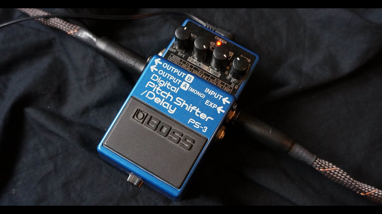
(Boss PS-3)
While I can’t find any specific documentation on the inner workings of the pedal, I was able to approximate the effect design relatively easily in Max/MSP. I can fairly assuredly say the effect is digital rather than analog based, as when using the pedal in the default delay settings there are noticeable glitches are artefacts from changing the delay time, rather than there being a smooth “doppler” effect that is found on most analog delays. These artefacts are part of the appeal of using this pedal for me, and should hopefully be easy to replicate as I have produced similar sounds with the Maximilian audio library before. This article also notes that the PS-3 has the same maximum delay time as the DD-5, which was sold around a similar time and most likely is based on similar technology, though I can’t be certain of this.
In terms of the pitch shifting effect, I feel fairly confident that the pedal employs the commonly used pitch shifting technique of driving the delay time on a delay line with a phasor or some kind of constantly ramping signal, and then simple inserts feedback into that delay line in order to achieve the cascading effect. There is some notable windowing to get a smoother pitch shifting sound and possible cross-fading between two offset delay lines; the degree to which I will incorporate this into my own design will really depend on what it sounds like ultimately. There is also a case of how memory will be available on the Teensy board, though I will have a better idea of that once I begin programming.
Despite being unintentional, the most important aspect of this pedal that I will be hoping to emulate is the ability to create noise and interesting textures using its stereo output capabilities, employing a no-input mixing technique as popularised by various noise artists. I will research into how best to implement this once the effect design is down and I’ve started development of the code on the Teensy.
Besides the Boss PS-3, my project will also incorporate various features from other delays that I think will be useful for versatility and expression. My hope is that the final result will be fairly multi-functional and feature a relatively extensive array of parameters for a delay pedal.
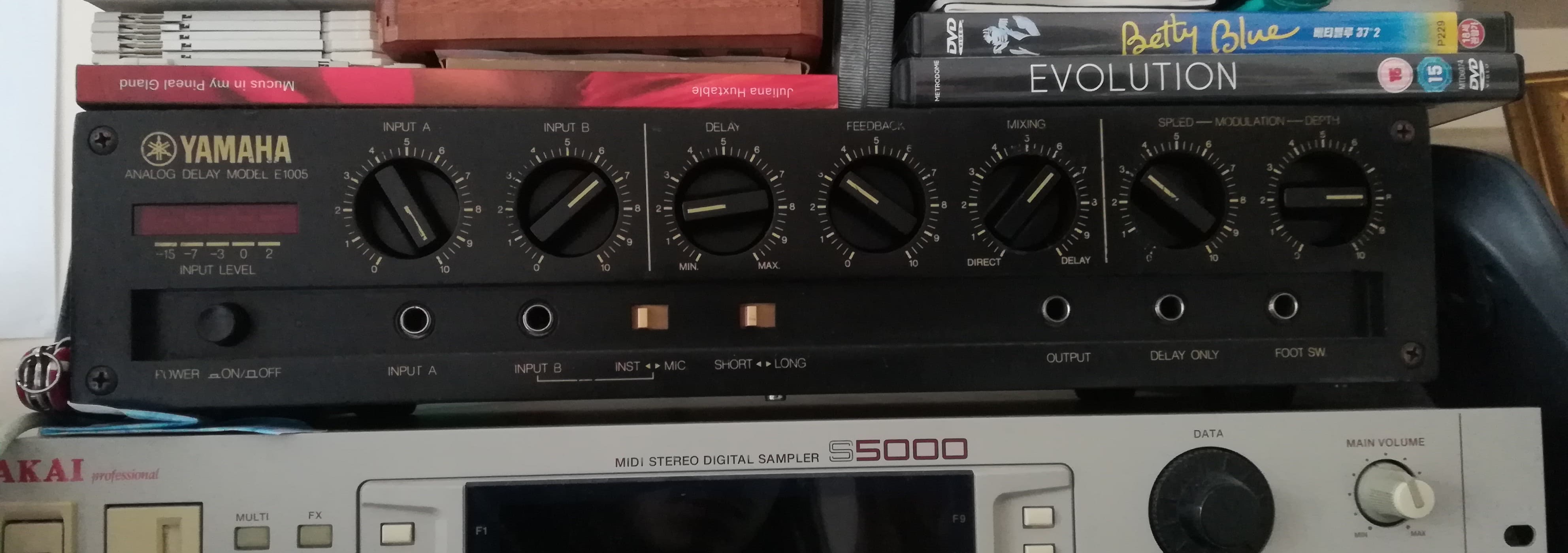
(Yamaha E1005)
The first of these that I would like to focus on are BBD (bucket-brigade device) based delays. The effect is implemented in a wide array of effects processors, especially those manufactured in the 1970s in particular. I will however be focusing on the Yamaha E1005 as that is the only one I personally own and is what I am drawing inspiration from.
The key feature of this Delay that I’d like to implement in my own effect are the modulation parameters. These control the amplitude and speed of an LFO that modulates the delay time parameter. This results in pitch modulation as BBD chip delays feature the pitch-shifting doppler effect when varying the delay time. This functionality allows for an array of time-based effects like vibrato, chorus, flanging and phasing so this is definitely something I will try to implement myself. Something that I noticed when I started to look more in depth to how the effect was put together, is that the amplitude of the waveform needs to actually scale with the delay time itself. The amplitude of the wave at the maximum delay time would go out of range if it remained at the same value for the smallest delay time, so maximum amplitude does not necessarily mean the same value across the range of possible delay times. It’s possible that the fully analog circuit does not need to take this into account due to its design but it will definitely have to be a design consideration with the digital implementation.
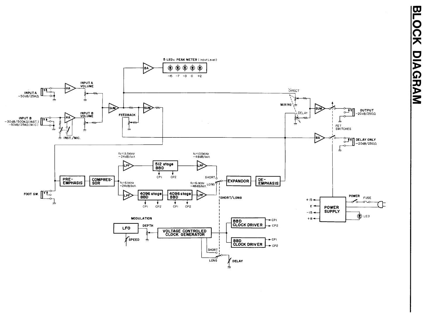
(Yamaha E1005 circuit diagram)
Another unit that I’m partially basing my own design on is the Korg Monotron Delay. This is actually a fully analog synth which also features a built-in delay. The synth aspect is fairly minimal, with a simple sine wave being controlled with a ribbon keyboard with pitch modulation from an LFO. What appeals to me about this device however is the inclusion of a filter in the signal patch of the delay. It’s not uncommon for analog delays to feature a filter in order to remove unwanted noise, which contributes to the distinctive darker sound of BBD delays. In most software implementations of delays that I’ve made I’ve included a low pass filter in order to somewhat imitate this sound. However, the filter on the Monotron is more resonant then u would find on a normal analog delay, and also allows the user to vary the cutoff. When combined with the delay feedback this can result in some interesting noises and textures which I hope to be able to emulate somewhat.

(Korg Montoron Delay)
The first stage of development was to create a prototype in the audio software development environment, Max/MSP. I decided this would be a good idea as I am quite familiar with Max and could produce something fairly quickly, and I wanted to know how creatively effective my initial idea for the project would be in practice. Most aspects of the effect design were things that I had already programmed before, so it wasn't long before I had a working prototype.
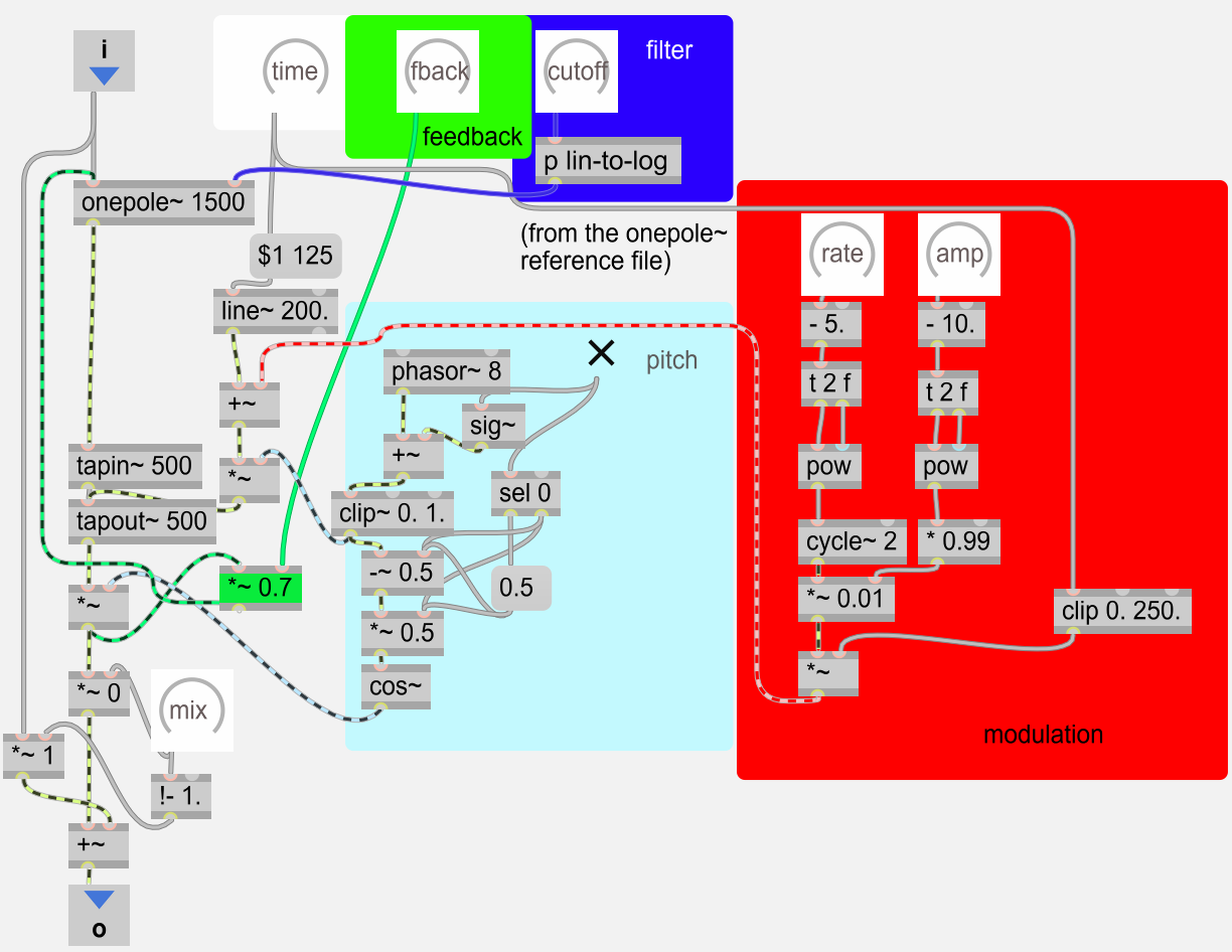
(Max/msp prototype)
For the most part everything worked as I expected it to, however there were a few elements of the design that I had to change my plans for somewhat. The first of these was the filter. I had originally thought to use a resonant filter and allow the user to control the resonance amount. When I tried this however, I realised that any resonance would be amplified by the feedback parameters, as when the repeats build up the peak in the filter is being consistently added to. Another thing I realised was that the amplitude of modulation needed to scale with the delay time. A large amount of modulation wouldn't work at lower delay times as the delay time value would dip below the minimum buffer size. Similarly, were I to set the modulation amplitude to a low value to avoid this issue, there would then be hardly any variation at the higher values. I based my implementation here on the modulation tutorial found in the Max/MSP documentation.
With a prototype fleshed out in Max, I’m now ready to begin development on the board itself. Having never done any real electronics before, the first step was to just construct a simple circuit and see if I could program the board to do something. I used the Arduino projects book to start learning about how to build circuits and constructed the first LED example to determine if the board was working properly. I quickly realised that the Teensy I had ordered was the headerless version, which does not come with pins soldered to the board, so for my initial testing I placed the Teensy on top of pins that were plugged into the Breadboard. This actually worked fine and I managed to get the LED circuit to light.
The next phase was to see if I could get any sound of the audio shield. For this I put the shield in place, plugged in the pins in and then places the audio board on top. On the software side, I loaded up the example patch that PJRC provide for using the Teensy audio library which provides a steady beep. I didn’t end up getting any sound this way however even though the LED continued to be lit and I soon discovered that it would be necessary to go straight to soldering if I hoped to get any sound from it. I wanted to avoid soldering too early because I wanted to be able to start development of the code as soon as possible and because I’m fairly inexperienced at it and making any major mistakes could end in halting development even further while I replace the board. Ultimately however, once soldered the board worked as expected and I managed to get some output from the headphone jack. The output itself had a lot of background noise which was initially troubling, but when plugging it in at another power source it was completely clean and the noise it had picked up before was just from the computer I was programming it from. At this stage the hardware is ready for me to start developing the code and that’s what I plan on spending the next
Once I had begun to code with the audio library, I quickly realised that its delay would not work for this project. The delay needed to be a variable delay line, so that changing the delay time would result in the Doppler effect; this is crucial in order to achieve modulation and pitch-shifting effects. The delay that is included in the audio library does not feature an input to change the delay time via a signal, so I begun to try and code my own delay object.
Coding new objects for the Teensy audio library is complex, but there is a fair amount of documentation provided by PJRC. The Audio library deals in blocks of samples at a time. These blocks usually contain 128 samples. Audio blocks are essentially just arrays containing samples, and operations can be performed on the data inside these blocks
I used the information provided by the audio library documentation and studied the existing objects that are included as part of the audio library, and managed to create a simple delay effect.
#include <Arduino.h> #include "effect_mod.h" void AudioEffectMod::update(void){ audio_block_t *output; int delayBlocks; delayBlocks=delayTime/AUDIO_BLOCK_SAMPLES; playHead=playHead%DELAY_QUEUE_SIZE; buffer[playHead]=receiveReadOnly(); output=buffer[((DELAY_QUEUE_SIZE-delayBlocks)+playHead)%DELAY_QUEUE_SIZE]; playHead++; transmit(output,0); release(output); }
Whilst I wasn't basing this on any specific algorithm, I tried to think about how the tapin and tapout objects in Max/msp works. All this code does is continuously record audio into a buffer and then output the samples from the buffer a certain number of samples ago (determined by the delay time)
The code I had written worked fine for a digital delay with no modulation capabilities. However, I needed to create a variable delay line. The way this is generally achieved for digital delays is using a method called "linear interpolation". The idea behind this as I understand it is that when working with digital audio, rather than being able to smoothly transition between delay times, jumps will occur because you are working with a discrete array of samples rather than a continuous signal. Linear interpolation is use to make an estimated value between discrete data points; in the instance of audio, that means estimating samples that fall inbetween the samples in the digital audio signal.
Whilst I felt as though I understand the general principle of this, I found that putting this algorithm into practice in my own delay code was incredibly difficult. There were various examples online, but I didn't fully understand how their implementations worked.
I ended up losing a lot of time trying to write a linear interpolation delay, until eventually I realised it would be better to try and incorporate one of the open source examples I found online into my project. I had never begun the programming stage thinking that I would need to code my own delay from scratch, so I was wasting time that I could have spent trying to get the rest of the effect and the electronics working.
After reading some posts about the subject of linear interpolation delays on the PJRC forums, I found a user that had written their own modulatable delay effect for the Teensy, and had published their code with an open source license on github. This is the delay code that I ended up using in my final project.
Once I had a modulatable delay effect, progress on the project went a lot faster. I ordered some potentiometer parts and a breadboard friendly audio jack off of PiHut, and begun development on the interface portion of the device.
I used the tutorial on the Arduino website to get a single potentiometer working which ended up being quite straightforward. When I tried to add more potentiometers into the circuit however, I saw that the two potentiometers were essentially acting as two halves of the same potentiometer: the first one gave me values in the range of (0-500) and the second one (500-1000). I then realised that this was because the potentiometers reduce the resistance of a circuit, and that they were both part of the same circuit. I tried to connect them in parallel rather than series and found that this fixed the problem and I was able to read data from multiple potentiometers.
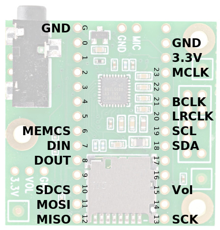
(Teensy Audio Board Diagram)
An additional problem arose however, as when I tried to connect more potentiometers, I found that using certain pins on the Teensy led to either the audio crashing or the board not being able to start. Upon further testing, I discovered that pins A9, A7, A6, A5 and A4 all caused problems. When looking at the page for the audio board on the PJRC website, I realised that this pins all perform essential functions when the Teensy is plugged into the audio board. Pins A5 and A4 however had the effect of preventing the audio chip from starting up whilst they were in use, but if used after the audio chip had already started operation then the pins could be used as normal. The compromise I made then was to use one of these pins and simply unplug the potentiometer from the breadboard before I turned it on. Were I to develop this project past the prototype stage however I would look into using another board to increase the number of ADCs the Teensy can use.
Once the potentiometers were working, I shifted my attention back to developing the effect portion of the device. In order to find out how much memory to assign to the delay buffer, I looked at the ".ino" file that was featured on the github repository where I originally found the delay code. The mod delay code accepts a signal input for the delay time, and so to control the delay normally I made use of the "AudioWaveformDC" object which generates an audio signal of fixed value. This worked well when controlled by the potentiometer and I quickly had a functional digital delay sound.
Next, I looked into trying to introduce some modulation. Whilst I could control the delay time with a sine wave signal, I quickly realised that when mixed with the DC signal the Doppler effect was incredibly pronounced. I ended up reducing the ampltiude of the LFO signal to a tiny amount (I divided by an extra 3000 after normalisation) and this worked well enough. I am not sure why the effect was so severe, but it worked nonetheless.
The last thing to include was the pitch-shifting effect. For this, I used the same algorithm I had used in max of driving the delay time using a sawtooth. The sawtooth was normalised from 0-1 and then the amplitude was controlled by a potentiometer. This differed slightly from the Max/msp implementation as that used the delay time value to set the pitch-shifting interval.
At this point I realised that I did not have enough potentiometers or usable analog pins to add in a controllable filter, and so left this part of the effect out for the time being. Apart from that though I had succesfully created one instance of the delay effect.
Before I could incorporate more instances of the delay effect, I needed a way to change which effect was being edited. I had initially thought to use a three way switch for this, but upon research discovered that this would require use of the analog pins and I had already ran out of those. The solution I had thought of for this was to instead use a button to a cycle through the effects. This would make use of the digital pins instead, of which plenty were free, and didn't require me to have to wait for any new parts as I already had buttons from other projects.
Using the arduino tutorials again, I was quite easily able to read data in from one button and ended up adding in another in order to switch between input sources. On the code end, I used a boolean variable called "stateWaiting" to determine whether the button had been pressed (digitalRead is true), and then ran the code I wanted the button to control when both "stateWaiting" was true and the button had been released (digital read is low).
//button for changing which delay is being changed if(digitalRead(buttonPin))stateWaiting=true; else if(stateWaiting&&!digitalRead(buttonPin)){ state=(state+1)%3; stateWaiting=false; Serial.println(state); }
On the subject of audio input, I decided it was time to add a line-in input to the device. Up until this point I had been testing the project with a file being read from the SD card. It was paramount that the line in functionality would work however as the device had been intended to function as a multi-effects processor and having a stereo line in could be used in conjunction with the stereo out to create the no-input mixing effect that was the original inspiration for the project. Getting a line-in input was easier than I thought it would be: it required three wires to be soldered to the pin holes on the audio board marked "L", "R" and "G". There were two grounds, but as I was using a stereo input jack both sides could share the same ground. Despite not being able to find much in the way of a tutorial on how to hook up the audio jack to work, when testing out the circuit with the headphone jack on the breadboard and running the line-in arduino sketch included as part of the audio library tutorials, it worked without any problems.
I now essentially had a working effects pedal, but it only had one delay. The next thing I looked into was trying to expand the code to the original idea of having three delays connected in serial. I thought to just hard code this initially to see if I could get it to work, and then encapsulate later. I copy and pasted all the delay code and changed the variable names, but found that, even though the code was identical, I could only ever get one to work at a time. Trying to use two just resulted in glitchy sounds and noises which were interesting, but I wanted to be able to create conventional delay sounds as well. I initially thought there was an issue with the buffer size, but I had halved the value that determined the buffer size which should have worked fine: previously it was the maximum I could achieve with the system ram, and so now that there were two effects, half of that value should have been acceptable amount. I then realised that the problem wasn't with the size of the buffer but the buffers themselves. There was only one buffer array, and so both delays were trying to record to the same buffer. I liked the sounds that this made and thought that it could be a potential feature incorporated into the design at some point, but for the time being I fixed it by creating a new buffer for the extra delay. This worked and I soon had two and then three identical effects connected in series.
Around this time, I had decided to test out the effect with the newly added line-in input. I tried it with a guitar first, and once I used the effect with a melodic input source I realised that the pitch-shifting algorithm did not actually work at all. It would only ever shift downwards. After experimenting with the waveform shapes I realised that, despite Max/msp only requiring a single waveform to shift in either direction, this delay algorithm needed a sawtooth to shift downwards, and a reverse sawtooth to shift up. I created a new mixer object to switch between these two waveforms, and controlled the amplitude of the waves with the delay time value. This not only worked to fix the pitch-shifting problem, but also freed up a potentiometer on the breadboard. This allowed me to add in the variable filter that had been in the initial design. I also had to add in another button to turn off or on the pitch-shifting effect, as previously I could set the pitch-shifting dial to 0 to turn it off. At this point the effect portion of the project was fully functional and I had incorporated almost everything that I had originally set out to include.
I had decided to save testing no-input mixing for the end, after I had documented and recorded every other aspect of the project. This was because I have previously heard it said on various forums that the resultant high audio signals can potentially damange audio equipment and I was concerned that if I fried anything on the Teensy board then I wouldn't be able to continue with the project. I have personally never found this to be the case in my own experiments with no-input mixing, but I thought it was better not to take the risk.
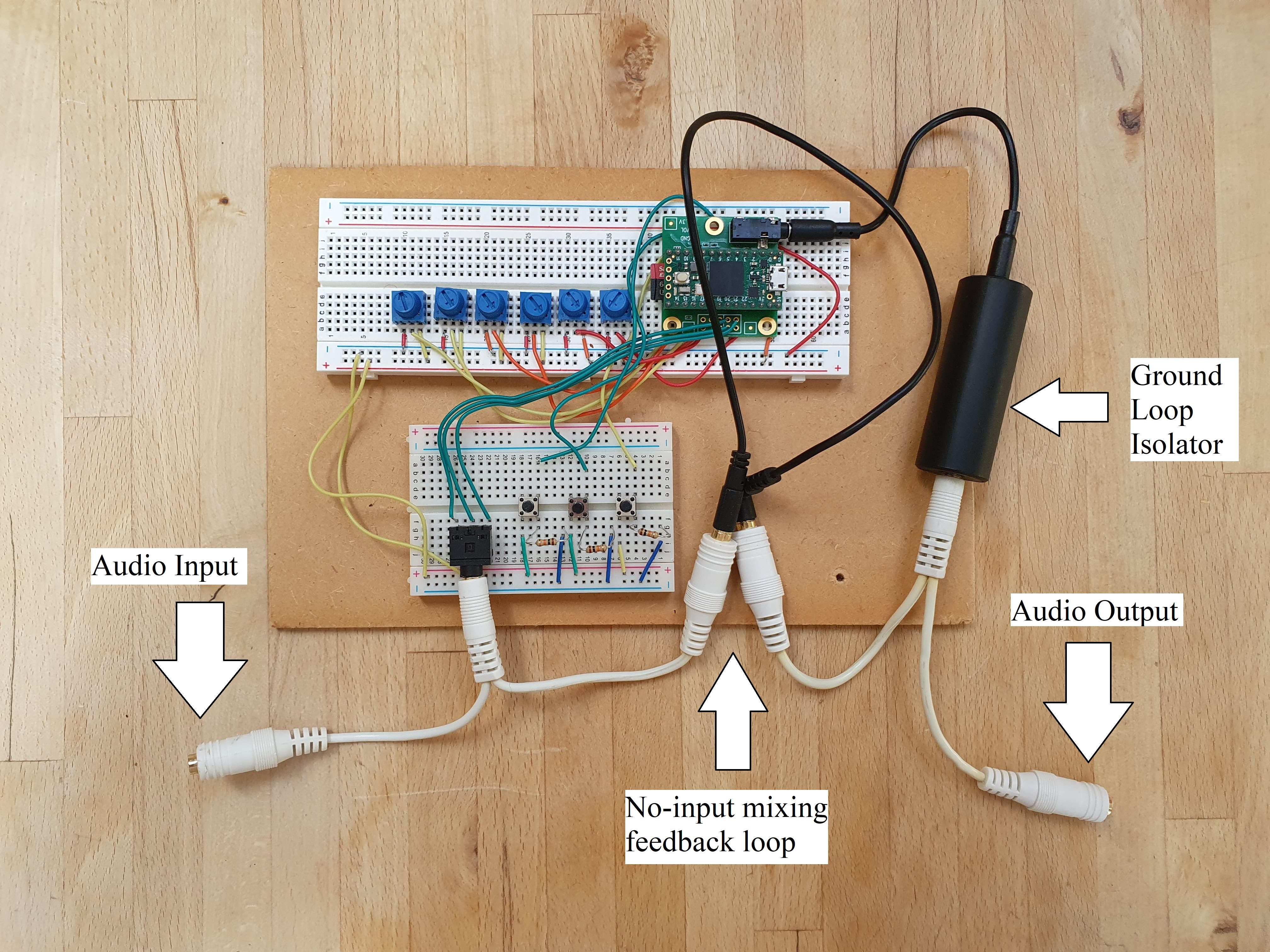
(Labelled Photo of Final Project)
I had wanted no-input mixing to be an integrated part of the design, and so I felt as though the user should not have to mess around with any cables in order to use the device in this way. My plan was to split the stereo output and input into their respective left and right channels, than take have a permanent audio cable going from the right output into the right input. The right channel could then be selected as the input source using the input select button. As this project is for a mono effect, the loss of stereo wasn't important, although the audio board does feature more inputs and outputs so this same design could probably be adapted for a stereo effect as well.
These method worked and I was able to succesfully use the device for no-input mixing. It sounded different from the Yamaha E1005 or Boss PS-3 but then this was to be accepted as no-input mixing is a widly unpredictable method of sound creation and the unique sound is part of the reason why I thought this would be a worthwhile idea to pursue. One of the nuances with using no-input mixing with this particular device is that it can sometimes to be hard to start creating a sound, often no sound will initially be produced at all unless the delays are set to fully dry which is the opposite to how the Boss PS-3 functions when used in this way. Once the sound has been created though, then playing with the parameters can have interesting and unpredictable effects that lend themselves well to improvisation and creative exploration. Overall, I'm quite happy with how this aspect of the project ended up and it's fairly close to my original intention whilst also producing some different sounds from what I had originally imagined would be possible.
Though I'm overall quite happy with how the project turned out, it became apparent during testing that aspects of the interface did not work as well as they could. For example, switching between effects immediately set all the parameters of the effect being edited to whatever positions the potentiometers were in. If I continue to work on this project, I will alter the code so that parameters are only updated when its corresponding potentiometer is changed. Also, because of the lack of a three-way switch, it wasn't always clear which effect was being edited. I would either go back to the original idea of using a switch or having some kind of display that shows the current effect number. There is also the problem detailed earlier with the audio not being able to start without unplugging one of the potentiometers before turning it on. This is something that I would like to fix if I were to ever take this design off the breadboard.
There are some extra features that I think would be really worthwhile to include, most notably some form of MIDI implementation. I had wanted to add this from the beginning but was aware that I probably would not have time. I think it would be very interesting to have a delay that takes input from MIDI note data so it can be played as an instrument. This would really open up the sound design possibilities and allow for effects such as Karplus-strong string synthesis among other things. I also think a stereo mode would be a great addition. I had decided to make the device mono as stereo would have required doubling the number of delay times and therefore halving the maximum delay time for each effect, which I already felt was quite low. However, there could have been the option to switch between a long mon and a short stereo mode; or, a possibly ram expansion could be used though this would require coding a new delay effect to read and write data to and from the extra ram.
Otherwise I think the project was broadly succesful, and I look forward to using it in future music projects and possibly even live performances.